
On a previous post, I made an introduction about NVMe, NVMe-oF and RDMA for network engineers. In this post, I’m going to talk about RDMA over Converged Ethernet (RoCE) and, more specifically, how to implement and configure the QoS part of RoCEv2 on the Cisco Nexus 9300 series.
What is RoCE?
RDMA over Converged Ethernet (RoCE – pronounced “Rocky”) is a network protocol that allows Remote Direct Memory Access (RDMA) over an Ethernet network. It does this by encapsulating an InfiniBand transport packet over Ethernet. There are two different RoCE versions:
- RoCEv1 – Ethernet link layer protocol (Ethertype 0x8915) that allows communication between any two hosts in the same Ethernet broadcast domain. So, layer-2 only, not routable.
- RoCEv2 – Enhances RoCEv1 with a UDP/IP (IPv4 or IPv6) header and adds layer-3 routability. RoCEv2 is also known as Routable RoCE.
And if you want to know more about RDMA, you can find here an introduction to NVMe, NVMe-oF and RDMA.
To use RoCE, you need to have RDMA-capable Ethernet NICs (rNICs) on the source (servers) and target (storage) hosts.
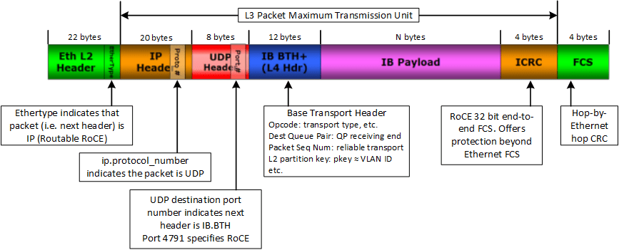
RoCEv2 packet details
- The RoCEv2 protocol exists on top of either the UDP/IPv4 or the UDP/IPv6 protocol.
- Uses UDP well-known destination-port number: 4791 by default.
- The UDP source-port serves as an opaque flow identifier that can be used by network infrastructure for packet forwarding optimizations. Like equal-cost multi-path (ECMP).
- Although in general the delivery order of UDP packets is not guaranteed, the RoCEv2 specification requires that packets with the same UDP source port and the same destination address must not be reordered.
- In addition, RoCEv2 defines a congestion control mechanism that uses the IP ECN bits for marking.
RoCEv2 packet format
How to support RoCEv2 on the network
A RoCEv2 network fabric should use various intelligent congestion control technologies to eliminate the potential packet loss and high latency of a traditional Ethernet network. Because the goal is to have a zero-packet-loss, low-latency, and high-throughput network for RoCEv2 distributed applications, meeting the stringent performance requirements of these applications. This includes:
802.1Qbb Policy Flow Control (PFC)
PFC, which is also referred to as Class-based Flow Control (CBFC) or Per Priority Pause (PPP), is a mechanism that prevents frame loss that is due to congestion. PFC is similar to 802.3x Flow Control (pause frames) or link-level flow control (LFC). However, PFC functions on a per class-of-service (CoS) basis: When a buffer threshold is exceeded due to congestion, 802.3x flow Control or LFC sends a pause frame to its peer to pause all data transmission on the link for a specified period of time. When the congestion is mitigated, when traffic comes under the configured threshold, a resume frame is generated to restart data transmission on the link.
Pause Frame
In contrast, during congestion, PFC sends a pause frame that indicates which CoS value needs to be paused.
A PFC pause frame contains a 2-octet timer value for each CoS that indicates the length of time that the traffic needs to be paused. The unit of time for the timer is specified in pause quanta. A quanta is the time that is required to transmit 512 bits at the speed of the port. The range is from 0 to 65535. A pause frame with a pause quanta of 0 indicates a resume frame to restart the paused traffic. PFC asks the peer to stop sending frames of a particular CoS value by sending a pause frame to a well-known multicast address. This pause frame is a one-hop frame that is not forwarded when received by the peer. When the congestion is mitigated, PFC can request the peer to restart transmitting frames.
As we can see below, with PFC, we can have lossless and lossy priorities at the same time on the same Ethernet wire by sending a pause frame to only one (or some) queue without impacting the other queues:
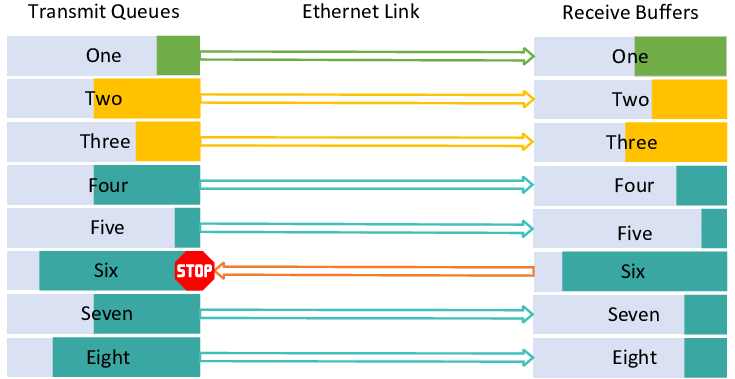
One important point to remember is: PFC is propagated on a hop-by-hop basis. And PFC frames are sent from the node that has experienced congestion toward the sender. For example, from one switch to another switch, then from a switch to a server’s NIC.
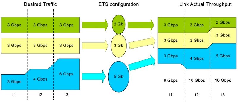
802.1Qaz Enhanced Transmission Selection (ETS)
With ETS, specific bandwidth is assigned to each of the CoS. It prevents a single traffic class from hogging all the bandwidth and starving other classes. And when a given load doesn’t fully utilize its allocated bandwidth, it is available to other classes.
Data Center Bridging Control Protocol (DCBX) – 802.1Qaz [optional]
DCBX negotiates Ethernet capability: PFC, ETC, and CoS values between DCB-capable peer devices. It is not mandatory, but it simplifies the management. DCBX is simply LLDP with new TLV fields.
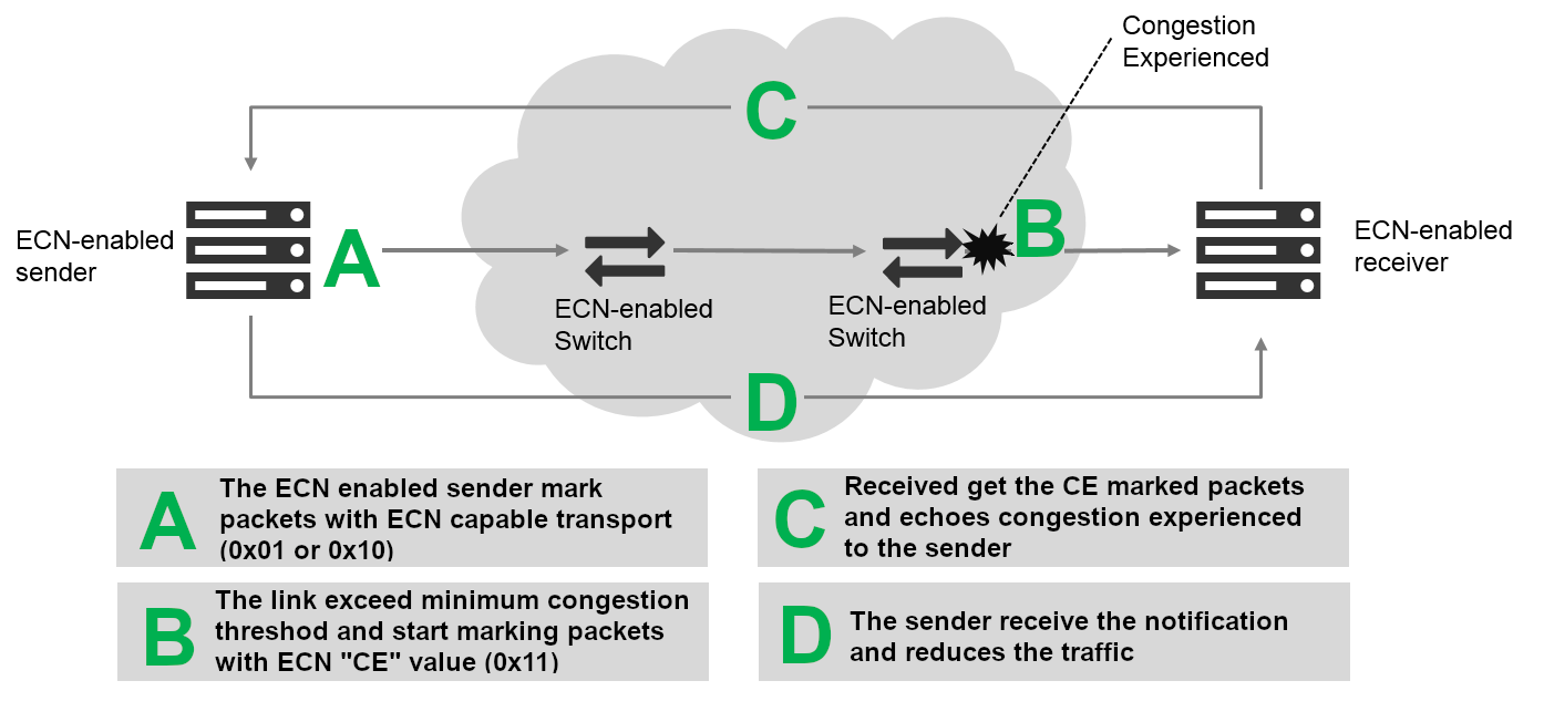
802.1Qau Explicit Congestion Notification (ECN)
ECN is an extension to WRED that marks packets instead of dropping them when the average queue length exceeds a specific threshold value. When configured with the WRED ECN feature, switches, routers, and end hosts use this marking as a signal that the network is congested to slow down sending packets.
>PFC performs by per-hop behavior, which at times might take more time than others to propagate congestion information to the sender. With ECN, congestion on any network device is propagated immediately to the endpoints, and traffic is marked on any network device that experiences congestion.
In case of congestion, the network device re-marks the packet with ECN Congestion Encountered (0x11) but does not send anything to the sender. The re-marked packet arrives at the destination, and the destination sends a notification to the sender to reduce the traffic.
ECN Values
ECN uses the two least significant (right-most) bits of the Traffic Class field in the IPv4 or IPv6 header to encode four different code points:
0x00 – Non ECN-Capable Transport (Non-ECT)
0x10 – ECN Capable Transport 0 (ECT-0)
0x01 – ECN Capable Transport 1 (ECT-1)
0x11 – Congestion Encountered (CE)
When both endpoints support ECN, they mark their packets with ECT-0 or ECT-1. Network equipment treats the ECT-0 (0x10) and ECT-1 (0x01) markings as equivalent. If the packet traverses an active queue management queue (a queue that uses RED or WRED) that is experiencing congestion and the corresponding router supports ECN, it may change the code point to CE (0x11) instead of dropping the packet. At the receiving endpoint, this congestion indication is echoed back to the transmitting node to signal it to reduce its transmission rate.
Note: not all RoCE Ethernet adapters (rNIC) support ECN for congestion control, but all Mellanox adapters from ConnectX-4 onward do so.
PFC is working on a layer-2 network. With layer-3, we need to use ECN. That means all the routers and switches along the path need to support ECN.
Using PFC and ECN together
For optimal RDMA performance in changing and dynamic network environments, both PFC and ECN can be used together. In that case, congestion caused by traffic patterns such as incast can be easily mitigated with ECN, because capabilities that exist anywhere in the data path congestion are signaled to the endpoints. However, if congestion is experienced close to the endpoints and caused by a burst application on the sender, PFC efficiently mitigates and manages the congestion by slowing down the sender. Where PFC and ECN are used together, ECN should be the primary congestion management mechanism and PFC the fail-safe.
>RoCE can also be deployed using just PFC or—with advanced RoCE adapters, such as those from Mellanox— with just ECN. Using only PFC or ECN, performance for ordinary applications can be satisfied, but the highest performance is usually achieved only by coupling PFC and ECN.
Nexus 9300 series QoS details
Let’s see some details about the quality of service part of the Cisco Nexus 9300-series.
RoCEv1/v2 support and license
- Cisco Nexus 9300 Series switches in NX-OS mode support the transport of RDMA over Converged Ethernet (RoCE) V.1 and V.2 protocols natively. It does not require a specific license.
Cisco Nexus 9300 QoS Golden-rules
- QoS is enabled by default and cannot be disabled.
- CoS and DSCP are trusted by default.
- Use QoS-Groups to tie policies together.
- Queuing and QoS policies are applied to a physical interface or at the system level.
- PFC-auto is the default PFC state of the interfaces.
PFC configuration on NX-OS
You can configure PFC on a per-port basis to enable the no-drop behavior for the CoS as defined by the active network QoS policy.
The configuration is done at the interface level:
switch(config)# interface ethernet 7/5
switch(config-if)# priority-flow-control mode [auto|off|on]
PFC can be configured in one of these modes:
- auto [default]—Enables the no-drop CoS values to be advertised by the DCBX protocol and negotiated with the peer. A successful negotiation enables PFC on the no-drop CoS. Any failures because of a mismatch in the capability of peers causes the PFC not to be enabled.
- on—Enables PFC on the local port regardless of the capability of the peers.
- off—Disables PFC on the local port.
PFC storm
A malfunctioning NIC on a host may not be able to receive any traffic from the network and keeps sending PFC pause frames toward the switch. Since lossless switch paths do not drop packets but decline receiving more packets when their buffers fill up, if the end-port queue is stuck for a long time, the buffers fill up not only for the target switch, but also on all switches with problematic port queues in the traffic forwarding path. This leads to endless PFC pause frames, also called a PFC storm, being observed on all switch ports along the path to the traffic source.
PFC Watchdog (PFCWD) on Nexus 9000
To mitigate this, the PFC watchdog can be used on the Nexus switches to prevent congestion. When the switches detect this situation on any egress queue, all the packets in the queue are flushed, and new packets destined to the same queue are dropped as well, until PFC storming is relieved. Of course, we are going to lose some packets with this solution, but only temporarily. Without this mechanism, the traffic of this queue is blocked all along the path until the faulty NIC is restarted or replaced.
The configuration can be done at the global or at the interface levels.
Here is an example of the command configured at the global level:
switch(config)# priority-flow-control watch-dog-internal on
And here is an example of the command configured at the interface level:
switch(config)# interface ethernet 7/5
switch(config-if)# priority-flow-control watch-dog-interval on
You may have to configure the different watchdog timers, depending on your needs.
You can see the current PFCWD status with the command:
switch# show queuing pfc-queue detail

slot 1
=======

Initting block addresses


+----------------------------------------------------+
Global watch-dog interval [Disabled]
Forced Global watch-dog [Disabled]
+----------------------------------------------------+

+----------------------------------------------------+
Global PFC watchdog configuration details

PFC watch-dog poll interval : 100 ms
PFC watch-dog shutdown multiplier : 1
PFC watch-dog auto-restore multiplier : 10
PFC watch-dog fixed-restore multiplier : 0
PFC watchdog internal-interface multiplier : 2
+----------------------------------------------------+
RoCEv2 on Cisco Nexus 9300 – QoS configuration examples
This is an example of a Nexus 9300 series configuration under NX-OS version 9.2(x).
Marking and classification part
First, let’s do a QoS class-map to match DSCP 26 / CoS 3 tagged RoCE packets:
class-map type qos match-all ROCE_CLASS
 match cos 3
 match dscp 26
The COS & DCSP values may be different between vendors’ documentation and implementations. You must adapt this classification depending on the host’s rNIC and storage configurations.
For instance, DSCP 26 here is the example used in the Mellanox NIC configuration page.
Then, we create a QoS policy-map to assign this class-map to the qos-group. This is for the classification part:
policy-map type qos ROCE_POLICY
 class ROCE_CLASS
 set qos-group 3
Queuing part
QoS queuing policy-map to ensure bandwidth to RoCE traffic (RoCE traffic is set to qos-group 3, which maps to c-out-8q-q3):
policy-map type queuing ROCE_QUEUING_OUT
 class type queuing c-out-8q-q3
  bandwidth remaining percent 50
  random-detect minimum-threshold 150 kbytes maximum-threshold 3000 kbytes drop-probability 7 weight 0 ecn
 class type queuing c-out-8q-q2
  bandwidth remaining percent 0
 class type queuing c-out-8q-q1
  bandwidth remaining percent 0
 class type queuing c-out-8q-q-default
  bandwidth remaining percent 50
!
ECN parameters are configurable per queue level. But ECN is disabled by default along with WRED; this is why we specify “ecn” at the end of the WRED line.
The result of this configuration is:
- If the packet threshold is below the minimum of buffer use (150 Kbytes here): transmit without ECN marking.
- Packet threshold between minimum and maximum (between 150KB and 3000KB of buffer use): randomly mark the packets (with probability 7) with ECN bits.
- If the packet threshold is above maximum (3000 Kbytes here), mark every traffic with ECN.
Important: the values of the minimum and maximum buffers here depend on your environment. This is only a configuration example. You need to test and fine-tune these values.
The QoS network class to identify RoCE traffic for no-drop:
class-map type network-qos ROCE_NETWORK_CLASS
 match qos-group 3
QoS network policy part
The QoS network policy to set JUMBO MTU and no-drop (pause) to RoCE traffic:
policy-map type network-qos ROCE_NETWORK_POLICY
 class type network-qos ROCE_NETWORK_CLASS
  pause pfc-cos 3
  mtu 9216
 class type network-qos c-8q-nq-default
  mtu 9216
The command “pause pfc-cos 3” here is used to define on which COS we will send the PFC signal if the switch receives a PFC.
Apply the created no-drop policy to the system:
system qos
 service-policy type network-qos ROCE_NETWORK_POLICY
Interface configuration part
Apply classification policy to the ingress interfaces and queuing policy to the egress interfaces.
Here, we also force PFC to be on (example here with interface ethernet 1/1):
interface Ethernet1/1
 priority-flow-control mode on
 service-policy type qos input ROCE_POLICY
 service-policy type queuing output ROCE_QUEUING_OUT
Optional PFC watchdog part
Last but not least, we can enable the PFC watchdog globally:
priority-flow-control watch-dog-interval on
Hosts Configurations
PFC and RoCEv2 configuration
The NIC configuration is dependent on the NIC vendor and version. Please refer to your NIC vendor documentation for the settings.
Important: the DSCP/COS values applied on the NIC must match the Cisco classification configuration. For example, here DSCP = 26 / ToS Dec. = 104.
ECN configuration
To configure ECN on the host, the Wikipedia page on ECN includes useful information: WikiPedia – Explicit Congestion Notification
Also for this, refer to your NIC vendor documentation for the settings.
Data Center Bridging Control Protocol (DCBX) host configuration
Another solution would be to use Data Center Bridging Control Protocol (DCBX). In this case, the rNIC and the switch must have DCBX enabled. Then, the PFC, DSCP/CoS values, and ECN settings are negotiated between the rNIC and the switch. Again, here, the NIC configuration to support DCBX depends on the NIC vendor and version.
Troubleshooting and debugging
Network side
On the switch, here is a list of checks we can do:
To check the status of the PFC on the interfaces (should be forced to ON on hosts facing interfaces):
show interface priority-flow-control
See the details of the policy-map applied to an interface:
show policy-map interface e1/7
To check the queuing statistics by interface:
show queuing interface e1/7
And to see the PFC Watchdog status and counters, globally or by interface:
show queuing pfc-queue [interface] [ethernet|ii] [detail]
Next, a good troubleshooting technique is to do a SPAN (or E/RSPAN) of the traffic to a probe. Here is an excerpt of the Wireshark output of one RoCEv2 packet:
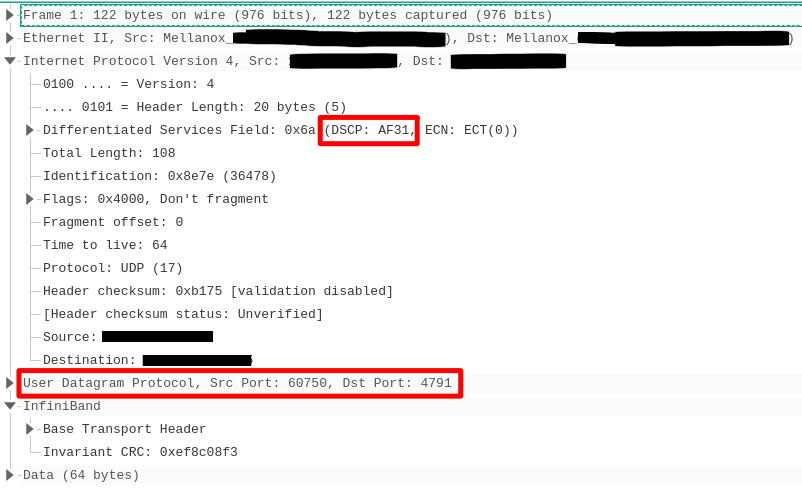
As we can see here, the DSCP marking corresponds to what we defined above (DSCP 26/AF31). We can also see the UDP encapsulation with the destination port 4791 and then the InfiniBand parts below.
Hosts side
An important point to remember is that because RDMA traffic bypasses the kernel, it cannot be monitored using tcpdump, Wireshark, or other similar tools. Except if the NIC is able to monitor this kind of traffic.
With NVIDIA/Mellanox ConnectX cards, there is a special flag to activate with ethtool.
With this, we can see RoCE traffic with a normal tcpdump command, for example:
# tcpdump -i enp5s0 dst 10.10.10.120
listening on enp5s0, link-type EN10MB (Ethernet), capture size 262144 bytes
10:47:39.820296 IP 10.10.10.10.64404 > 10.10.10.120.4791: UDP, length 80
10:47:39.820492 IP 10.10.10.10.64404 > 10.10.10.120.4791: UDP, length 20
10:47:39.820494 IP 10.10.10.10.64404 > 10.10.10.120.4791: UDP, length 20
10:47:40.818968 IP 10.10.10.10.53771 > 10.10.10.120.4791: UDP, length 80
10:47:40.819046 IP 10.10.10.10.53771 > 10.10.10.120.4791: UDP, length 20
10:47:40.819048 IP 10.10.10.10.53771 > 10.10.10.120.4791: UDP, length 20
10:47:41.819429 IP 10.10.10.10.62079 > 10.10.10.120.4791: UDP, length 80
10:47:41.819527 IP 10.10.10.10.62079 > 10.10.10.120.4791: UDP, length 20
References & Read More
- Meeting the Network Requirements of Non-Volatile Memory Express (NVMe) Storage with Cisco Nexus 9000 and Cisco ACI White Paper
- Cisco Nexus 9000 Series NX-OS Quality of Service Configuration Guide, Release 9.2(x)
- Cisco Nexus 9000 Series NX-OS Quality of Service Configuration Guide, Release 9.3(x)
- Alibaba Whitepaper on HPCC: High Precision Congestion Control
- Microsoft Whitepaper: RDMA over Commodity Ethernet at Scale
- Cisco Intelligent Buffer Management (AFD and DPP) on Cisco Nexus 9000 Series Switches White Paper
Hi sir, i searched on internet but i cannot find the solution. switch(config-if)# priority-flow-control watch-dog-interval On is not working. Is there wokaround or alternative command??
Hi,
I’m doing tests on a Nexus C9336C-FX2 on NXOS version 9.2.4 and it’s working:
(config-if)# priority-flow-control watch-dog-interval on
You should refer to the Cisco Nexus 9000 Series NX-OS Quality of Service Configuration Guide, because there is some exceptions, like: “PFC watchdog is not supported in Nexus 9500 with N9K-9400, N9K-9500 and N9K-9600 line card, with the exception of N9K-X9636PQ line cards (that support the PFC watchdog feature).”
If you do the command: “show run int ex/x all” you should see it off by default:
priority-flow-control watch-dog-interval off
I hope it helps.
Best Rgds,
Jerome