
After giving a two-days training to a customer on multicast technology, I take the opportunity to have my lab and the configurations ready to share with you a suite of five different multicast configurations examples. And, how to make some tests and troubleshooting. These examples are based on the labs I used to practice the CCIE R&S practical exam.
Content of the posts
- Any-source multicast (ASM) with static RP
- Any-source multicast (ASM) with auto-RP
- Any-source multicast (ASM) with anycast RP
- Any-source multicast (ASM) with bootstrap router (aka PIMv2)
- Source-specific multicast (SSM)
Including, for each topic:
- A network drawing
- The configuration details.
- The tests and debug outputs.
- When possible, a failover test and debug outputs.
- Some basic troubleshooting.
Any-source multicast (ASM) with auto RP
Lab design and description
The network design is the same for every scenario:
I use four layer-3 Cisco 3650 catalyst switches running IOS-XE. With layer-3 ptp interfaces between them to create a small layer-3 network. OSPF is running between the switches to advertise all the networks: the ptp networks, the loopback0 interfaces and the VLAN10 of SW-1, where is the multicast source.
For the multicast source, I use a laptop running two VLC instances, sending video stream traffic to 233.1.2.3 and 234.1.2.3, both on port 30’001.
The receiver will be simulated by the loopback0 interface of SW-4.
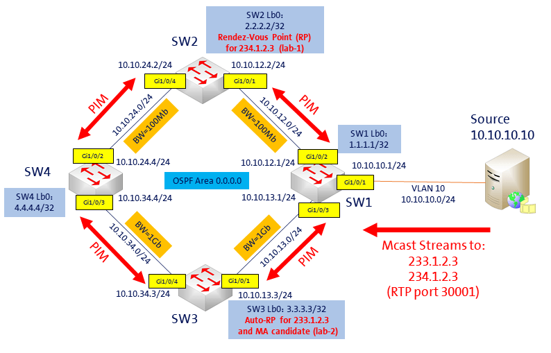
(Click on the image to see a larger version)
On this scenario, the loopback IP of SW3 (3.3.3.3) is the Auto-RP candidate for the group 233.1.2.3 and the mapping agent (MA).
The loopback IP of SW2 (2.2.2.2) is the static RP for the group 234.1.2.3. This was configured on the multicast lab-1.
Configuration
First, we need to configure PIM on the interfaces between the four switches, on the interface where is source is located (VLAN10 of SW-1), the interface of the clients or receivers (in this case, the loopback0 of SW-4) and on the RP interface (loopback0 of SW-3). For the PIM configuration, because we use Auto-RP, we have two choices:
- Use ip pim sparse-mode on the interfaces and add ip pim autorp listener on the four routers.
- Or, use ip pim sparse-dense-mode on the interfaces, on this case there is no need of the ip pim autorp listener.
For simplicity, as PIM was already configured on the multicast lab-1, I choose to use solution #1. Do not forget to also configure ip multicast-routing, like below:
SW-1,2,3,4:
SW-X(config)#ip multicast-routing
SW-X(config)#ip pim autorp listener

SW-1,2,3,4: on the ptp interfaces, VLAN10 of SW-1, lo0 of SW-2, and lo0 of SW-4:
SW-X(config-if)#ip pim sparse-mode
Now, we must configure the auto-rp on the SW-3. I created also an access-list 11, to limit to one single multicast group (233.1.2.3) for this RP:
SW-3:
SW-3(config)#access-list 11 permit 233.1.2.3
SW-3(config)#ip pim send-rp-announce lo0 scope 5 group-list 11
SW-3(config)#ip pim send-rp-discovery lo0 scope 5
!
SW-3(config)#int lo0
SW-3(config-if)#ip pim sparse-mode
Tests and debugging
Before IGMP join
First, let’s see the multicast-routing table on SW4:
SW-4#show ip mroute
IP Multicast Routing Table
Flags: D - Dense, S - Sparse, B - Bidir Group, s - SSM Group, C - Connected,
L - Local, P - Pruned, R - RP-bit set, F - Register flag,
T - SPT-bit set, J - Join SPT, M - MSDP created entry, E - Extranet,
X - Proxy Join Timer Running, A - Candidate for MSDP Advertisement,
U - URD, I - Received Source Specific Host Report,
Z - Multicast Tunnel, z - MDT-data group sender,
Y - Joined MDT-data group, y - Sending to MDT-data group,
V - RD & Vector, v - Vector
Outgoing interface flags: H - Hardware switched, A - Assert winner
Timers: Uptime/Expires
Interface state: Interface, Next-Hop or VCD, State/Mode

(*, 224.0.1.39), 00:06:19/stopped, RP 0.0.0.0, flags: DC
Incoming interface: Null, RPF nbr 0.0.0.0
Outgoing interface list:
GigabitEthernet1/0/2, Forward/Sparse, 00:06:19/stopped
GigabitEthernet1/0/3, Forward/Sparse, 00:06:19/stopped

(3.3.3.3, 224.0.1.39), 00:06:19/00:02:40, flags: PTX
Incoming interface: GigabitEthernet1/0/3, RPF nbr 10.10.34.3
Outgoing interface list:
GigabitEthernet1/0/2, Prune/Sparse, 00:00:10/00:02:48

(*, 224.0.1.40), 00:16:38/stopped, RP 0.0.0.0, flags: DCL
Incoming interface: Null, RPF nbr 0.0.0.0
Outgoing interface list:
Loopback0, Forward/Sparse, 00:16:38/stopped
GigabitEthernet1/0/2, Forward/Sparse, 00:06:20/stopped
GigabitEthernet1/0/3, Forward/Sparse, 00:06:20/stopped

(3.3.3.3, 224.0.1.40), 00:06:19/00:02:47, flags: LT
Incoming interface: GigabitEthernet1/0/3, RPF nbr 10.10.34.3
Outgoing interface list:
GigabitEthernet1/0/2, Forward/Sparse, 00:06:19/stopped
Loopback0, Forward/Sparse, 00:06:19/stopped
Here, we can see two dense-mode routes: (*, 224.0.1.39) and (*, 224.0.1.40), with the flag “D” for Dense. These two routes are for auto-RP. Auto-RP need to use dense-mode for the groups 224.0.1.39 and 224.0.1.40, to be able to send the information to the entire PIM domain. Here is, in summary, how it works:
- The candidate RP (cRP) send RP-announce messages to the group 224.0.1.39, to propose itself as an RP (UDP packets to port 496, every 60 seconds by default). These messages contain a list of multicast groups the cRP would like to be the RP for.
- The Mapping agent (MA) listen to 224.0.1.39 to collect all candidates-RP (cRP) information and elect which cRP will be RP for every group (based on highest IP address).
- The mapping agent send RP discovery messages to 224.0.1.40.
- The RP info embedded in the RP discovery message sent to 224.0.1.40 contains the best elected RP-to-group mapping information.
- All cRP listen and receive these messages to know who is the RP.
This is the reason why we need to use ip pim sparse-dense-mode on the entire multicast-domain, or the ip pim autorp listener command if we use ip pim sparse-mode. The ip pim autorp listener command causes the IP multicast traffic for the two Auto-RP groups, 224.0.1.39 and 224.0.1.40, to be PIM dense-mode (DM) flooded across the interfaces configured for PIM sparse-mode (SM).
Now, let’s verify the RP configuration/election on the four switches:
SW-X#show ip pim rp mapping
PIM Group-to-RP Mappings

Group(s) 233.1.2.3/32
  RP 3.3.3.3 (?), v2v1
    Info source: 3.3.3.3 (?), elected via Auto-RP
         Uptime: 00:01:38, expires: 00:02:19
Good, we can see the RP 3.3.3.3 is elected for group 233.1.2.3 via Auto-RP.
IGMP join
Now, let’s make an IGMP join for the group 233.1.2.3 on the loopback0 of SW-4.
SW-4#config t
SW-4(config)#int lo
SW-4(config-if)#ip igmp join-group 233.1.2.3
With PIM and IGMP debugging, we can see on SW-4, the IGMP join part, and then the PIM join sent to the two PIM neighbors:
SW-4:
IGMP(0): WAVL Insert group: 233.1.2.3 interface: Loopback0Successful
IGMP(0): Send v2 Report for 233.1.2.3 on Loopback0
IGMP(0): Received v2 Report on Loopback0 from 4.4.4.4 for 233.1.2.3
IGMP(0): Received Group record for group 233.1.2.3, mode 2 from 4.4.4.4 for 0 sources
(...)
PIM(0): Check RP 3.3.3.3 into the (*, 233.1.2.3) entry
PIM(0): Building Triggered (*,G) Join / (S,G,RP-bit) Prune message for 233.1.2.3
PIM(0): Insert (*,233.1.2.3) join in nbr 10.10.34.3's queue
PIM(0): Building Join/Prune packet for nbr 10.10.34.3
PIM(0):  Adding v2 (3.3.3.3/32, 233.1.2.3), WC-bit, RPT-bit, S-bit Join
PIM(0): Send v2 join/prune to 10.10.34.3 (GigabitEthernet1/0/3)
At this point, we can see on the multicast routing table of SW-4, the multicast traffic is coming through SW-3.
And we can also see traffic statistics with the command: show ip mroute count
SW-4#show ip mroute
IP Multicast Routing Table
Flags: D - Dense, S - Sparse, B - Bidir Group, s - SSM Group, C - Connected,
       L - Local, P - Pruned, R - RP-bit set, F - Register flag,
       T - SPT-bit set, J - Join SPT, M - MSDP created entry, E - Extranet,
       X - Proxy Join Timer Running, A - Candidate for MSDP Advertisement,
       U - URD, I - Received Source Specific Host Report,
       Z - Multicast Tunnel, z - MDT-data group sender,
       Y - Joined MDT-data group, y - Sending to MDT-data group,
       V - RD & Vector, v - Vector
Outgoing interface flags: H - Hardware switched, A - Assert winner
 Timers: Uptime/Expires
 Interface state: Interface, Next-Hop or VCD, State/Mode

(*, 233.1.2.3), 00:09:03/stopped, RP 3.3.3.3, flags: SJCL
  Incoming interface: GigabitEthernet1/0/3, RPF nbr 10.10.34.3
  Outgoing interface list:
    Loopback0, Forward/Sparse, 00:09:03/00:02:09

(10.10.10.10, 233.1.2.3), 00:09:03/00:01:51, flags: LJT
  Incoming interface: GigabitEthernet1/0/3, RPF nbr 10.10.34.3
  Outgoing interface list:
    Loopback0, Forward/Sparse, 00:09:03/00:02:09

(*, 224.0.1.39), 00:38:51/stopped, RP 0.0.0.0, flags: DC
  Incoming interface: Null, RPF nbr 0.0.0.0
  Outgoing interface list:
    GigabitEthernet1/0/3, Forward/Sparse, 00:38:51/stopped
    GigabitEthernet1/0/2, Forward/Sparse, 00:38:51/stopped

(3.3.3.3, 224.0.1.39), 00:38:51/00:01:58, flags: PTX
  Incoming interface: GigabitEthernet1/0/3, RPF nbr 10.10.34.3
  Outgoing interface list:
    GigabitEthernet1/0/2, Prune/Sparse, 00:01:51/00:01:08

(*, 224.0.1.40), 00:39:03/stopped, RP 0.0.0.0, flags: DCL
  Incoming interface: Null, RPF nbr 0.0.0.0
  Outgoing interface list:
    GigabitEthernet1/0/3, Forward/Sparse, 00:39:03/stopped
    GigabitEthernet1/0/2, Forward/Sparse, 00:39:03/stopped
    Loopback0, Forward/Sparse, 00:39:03/stopped

(3.3.3.3, 224.0.1.40), 00:38:57/00:02:47, flags: LT
  Incoming interface: GigabitEthernet1/0/3, RPF nbr 10.10.34.3
  Outgoing interface list:
    Loopback0, Forward/Sparse, 00:38:57/stopped
    GigabitEthernet1/0/2, Forward/Sparse, 00:38:57/stopped
SW-4#show ip mroute count
Use "show ip mfib count" to get better response time for a large number of mroutes.

IP Multicast Statistics
6 routes using 3372 bytes of memory
3 groups, 1.00 average sources per group
Forwarding Counts: Pkt Count/Pkts per second/Avg Pkt Size/Kilobits per second
Other counts: Total/RPF failed/Other drops(OIF-null, rate-limit etc)

Group: 233.1.2.3, Source count: 1, Packets forwarded: 86357, Packets received: 86357
  RP-tree: Forwarding: 2/0/0/0, Other: 2/0/0
  Source: 10.10.10.10/32, Forwarding: 86355/146/344/404, Other: 86355/0/0
Troubleshooting
Please see the multicast lab-1 post for other troubleshooting tips.
Auto-RP checks
To see the list of RP/group mapping: show ip pim rp mapping
SW-4#show ip pim rp mapping
PIM Group-to-RP Mappings

Group(s) 233.1.2.3/32
  RP 3.3.3.3 (?), v2v1
    Info source: 3.3.3.3 (?), elected via Auto-RP
         Uptime: 00:54:08, expires: 00:02:30
Be as specific as possible on the RP group range definition: add an ACL to limit your groups/channels.
We can also use the command: show ip pim autorp
SW-4#show ip pim autorp
AutoRP Information:
AutoRP is enabled.
RP Discovery packet MTU is 0.
224.0.1.40 is joined on Loopback0.
AutoRP groups over sparse mode interface is enabled

PIM AutoRP Statistics: Sent/Received
RP Announce: 0/0, RP Discovery: 0/2516
SW-4#
ICMP Ping to multicast group with static IGMP join
One very quick method to check your multicast configuration is to make a static IGMP join of the multicast group on the router close to your receivers, and then send an ICMP ping from the router close to the source, towards the IP of the multicast group. The “client” router must answer, also the clients who joined this group:
SW-4#show run int lo0
Building configuration...

!
interface Loopback0
ip address 4.4.4.4 255.255.255.255
ip pim sparse-mode
ip igmp join-group 233.1.2.3
end

SW-1#ping 233.1.2.3
Type escape sequence to abort.
Sending 1, 100-byte ICMP Echos to 233.1.2.3, timeout is 2 seconds:

Reply to request 0 from 4.4.4.4, 1 ms
SW-1#
Others posts of this series
- Any-source multicast (ASM) with static RP
- Any-source multicast (ASM) with auto-RP
- Any-source multicast (ASM) with anycast RP
- Any-source multicast (ASM) with bootstrap router (aka PIMv2)
- Source-specific multicast (SSM)