After giving a two-days training to a customer on multicast technology, I take the opportunity to have my lab and the configurations ready to share with you a suite of five different multicast configurations examples. And, how to make some tests and troubleshooting. These examples are based on the labs I used to practice the CCIE R&S practical exam.
Content of the posts
- Any-source multicast (ASM) with static RP
- Any-source multicast (ASM) with auto-RP
- Any-source multicast (ASM) with anycast RP
- Any-source multicast (ASM) with bootstrap router (aka PIMv2)
- Source-specific multicast (SSM)
Including, for each topic:
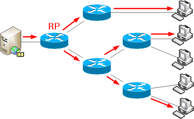
- A network drawing
- The configuration details.
- The tests and debug outputs.
- When possible, a failover test and debug outputs.
- Some basic troubleshooting.
Any-source multicast (ASM) with static RP
Lab design and description
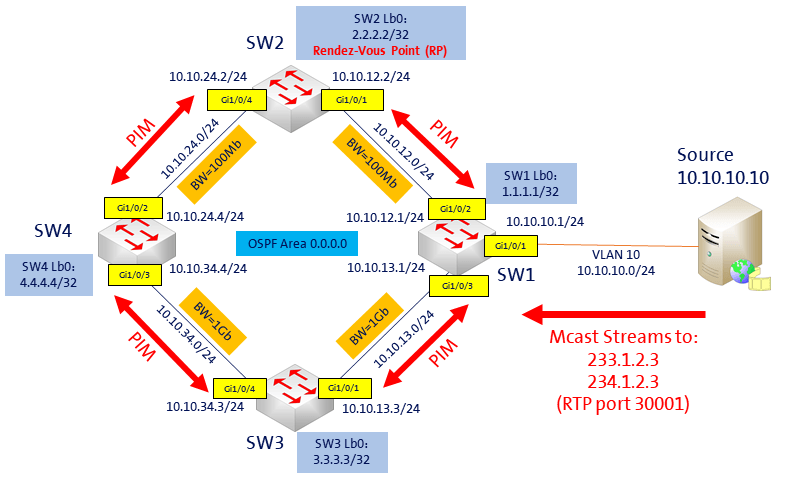
The network design is the same for every scenario:
I use four layer-3 Cisco 3650 catalyst switches running IOS-XE. With layer-3 ptp interfaces between them to create a small layer-3 network. OSPF is running between the switches to advertise all the networks: the ptp networks, the loopback0 interfaces and the VLAN10 of SW-1, where is the multicast source.
For the multicast source, I use a laptop running two VLC instances, sending video stream traffic to 233.1.2.3 and 234.1.2.3, both on port 30’001.
The receiver will be simulated by the loopback0 interface of SW-4.
(Click on the image to see a larger version)
This scenario is quite simple: the PIM configuration is done with PIMv1 and static-RP.
The loopback0 interface of SW-2 is the static RP. There is a faster bandwidth on the links SW1 – SW3 – SW4 comparing to SW1 – SW2 – SW4, to demonstrate later how the multicast traffic will switch from shared-tree to source-tree.
Configuration
First, we need to configure PIM on the interfaces between the four switches, on the interface where is source is located (VLAN10 of SW-1), the interface of the clients or receivers (in this case, the loopback0 of SW-4) and on the RP interface (loopback0 of SW-2). For this, we use PIM sparse-mode:
SW-1,2,3,4: on the ptp interfaces, VLAN10 of SW-1, lo0 of SW-2, and lo0 of SW-4:
ip pim sparse-mode
Now, we must configure multicast-routing and the static RP, on the four switches:
SW-1,2,3,4:
ip multicast-routing
!
access-list 12 permit 234.1.2.3
!
ip pim rp-address 2.2.2.2 12 override
Here, you can see two important points:
- First, I use an ACL to be the more specific possible. This to limit the RP only to the multicast group: 234.1.2.3. Because later, we will use another RP or SSM for the other group.
- I also added the “override” argument at the end of the RP definition. This is to be sure this RP configuration will not be replaced by any dynamic RP configuration.
Tests and debugging
Before IGMP join
Before doing any IGMP join, let’s look at the multicast routing table of SW-1:
SW-1#show ip mroute
IP Multicast Routing Table
Flags: D - Dense, S - Sparse, B - Bidir Group, s - SSM Group, C - Connected,
L - Local, P - Pruned, R - RP-bit set, F - Register flag,
T - SPT-bit set, J - Join SPT, M - MSDP created entry, E - Extranet,
X - Proxy Join Timer Running, A - Candidate for MSDP Advertisement,
U - URD, I - Received Source Specific Host Report,
Z - Multicast Tunnel, z - MDT-data group sender,
Y - Joined MDT-data group, y - Sending to MDT-data group,
V - RD & Vector, v - Vector
Outgoing interface flags: H - Hardware switched, A - Assert winner
Timers: Uptime/Expires
Interface state: Interface, Next-Hop or VCD, State/Mode

(*, 234.1.2.3), 00:00:04/stopped, RP 2.2.2.2, flags: SPF
Incoming interface: GigabitEthernet1/0/2, RPF nbr 10.10.12.2
Outgoing interface list: Null

(10.10.10.10, 234.1.2.3), 00:00:04/00:02:55, flags: PFT
Incoming interface: Vlan10, RPF nbr 0.0.0.0
Outgoing interface list: Null
As we can see, we have two routes, one shared-tree and one source-tree:
- The (*, 234.1.2.3) route is the shared-tree route. We can see the RP address is 2.2.2.2, and the incoming interface is the interface towards the RP (Gi1/0/2).
- The (10.10.10.10, 234.1.2.3) route is the source-tree route, as we receive multicast traffic from the source. The incoming interface where is the source (VLAN 10) and there is no outgoing interface.
Let’s do the same command on SW-2, the RP:
SW-2#show ip mroute
IP Multicast Routing Table
Flags: D - Dense, S - Sparse, B - Bidir Group, s - SSM Group, C - Connected,
L - Local, P - Pruned, R - RP-bit set, F - Register flag,
T - SPT-bit set, J - Join SPT, M - MSDP created entry, E - Extranet,
X - Proxy Join Timer Running, A - Candidate for MSDP Advertisement,
U - URD, I - Received Source Specific Host Report,
Z - Multicast Tunnel, z - MDT-data group sender,
Y - Joined MDT-data group, y - Sending to MDT-data group,
V - RD & Vector, v - Vector
Outgoing interface flags: H - Hardware switched, A - Assert winner
Timers: Uptime/Expires
Interface state: Interface, Next-Hop or VCD, State/Mode

(*, 234.1.2.3), 00:24:25/stopped, RP 2.2.2.2, flags: SP
Incoming interface: Null, RPF nbr 0.0.0.0
Outgoing interface list: Null

(10.10.10.10, 234.1.2.3), 00:24:25/00:02:51, flags: P
Incoming interface: GigabitEthernet1/0/1, RPF nbr 10.10.12.1
Outgoing interface list: Null
Here, we can see the source-tree (10.10.10.10, 234.1.2.3) have SW-1 (Gi1/0/1) as incoming interface. In this situation, the RP know the address of the multicast source (10.10.10.10) for the group 234.1.2.3, by maintaining a source-tree from the source to the RP.
For the shared-tree (*, 234.1.2.3), there is no incoming and outgoing interface. This is normal, because we have no receiver who has joined this group yet.
Note: at this moment, the multicast-routing table of SW-3 and SW-4 are empty.
IGMP join
Now, let’s make an IGMP join for the group 234.1.2.3 on the loopback0 of SW-4.
SW-4#config t
SW-4(config)#int lo
SW-4(config-if)#ip igmp join-group 234.1.2.3
With PIM and IGMP debugging, we can see on SW-4, the IGMP join part, and then the PIM join sent to the two PIM neighbors:
On SW-4:
IGMP(0): Received v2 Query on GigabitEthernet1/0/3 from 10.10.34.3
IGMP(0): WAVL Insert group: 234.1.2.3 interface: Loopback0Successful
IGMP(0): Send v2 Report for 234.1.2.3 on Loopback0
IGMP(0): Received v2 Report on Loopback0 from 4.4.4.4 for 234.1.2.3
IGMP(0): Received Group record for group 234.1.2.3, mode 2 from 4.4.4.4 for 0 sources
(...)
PIM(0): Send v2 join/prune to 10.10.24.2 (GigabitEthernet1/0/2)
PIM(0): Send v2 join/prune to 10.10.34.3 (GigabitEthernet1/0/3)
At this point, we can see on the multicast routing table of SW-4, the multicast traffic is coming through SW-3.
And we can also see traffic statistics with the command: show ip mroute count
SW-4#show ip mroute
IP Multicast Routing Table
Flags: D - Dense, S - Sparse, B - Bidir Group, s - SSM Group, C - Connected,
L - Local, P - Pruned, R - RP-bit set, F - Register flag,
T - SPT-bit set, J - Join SPT, M - MSDP created entry, E - Extranet,
X - Proxy Join Timer Running, A - Candidate for MSDP Advertisement,
U - URD, I - Received Source Specific Host Report,
Z - Multicast Tunnel, z - MDT-data group sender,
Y - Joined MDT-data group, y - Sending to MDT-data group,
V - RD & Vector, v - Vector
Outgoing interface flags: H - Hardware switched, A - Assert winner
Timers: Uptime/Expires
Interface state: Interface, Next-Hop or VCD, State/Mode

(*, 234.1.2.3), 00:26:30/stopped, RP 2.2.2.2, flags: SJCL
Incoming interface: GigabitEthernet1/0/2, RPF nbr 10.10.24.2
Outgoing interface list:
Loopback0, Forward/Sparse-Dense, 00:26:30/00:02:44

(10.10.10.10, 234.1.2.3), 00:26:30/00:02:21, flags: LJT
Incoming interface: GigabitEthernet1/0/3, RPF nbr 10.10.34.3
Outgoing interface list:
Loopback0, Forward/Sparse-Dense, 00:26:30/00:02:44

SW-4#show ip mroute count
Use "show ip mfib count" to get better response time for a large number of mroutes.

IP Multicast Statistics
3 routes using 1544 bytes of memory
2 groups, 0.50 average sources per group
Forwarding Counts: Pkt Count/Pkts per second/Avg Pkt Size/Kilobits per second
Other counts: Total/RPF failed/Other drops(OIF-null, rate-limit etc)

Group: 234.1.2.3, Source count: 1, Packets forwarded: 234870, Packets received: 234879
RP-tree: Forwarding: 15/0/0/0, Other: 21/6/0
Source: 10.10.10.10/32, Forwarding: 234855/143/344/390, Other: 234858/1/2
Shared tree to Source tree
Why the multicast traffic is coming through SW-3? Because the traffic already switched to source-tree (shortest path tree). And the shortest path from the receiver to the source is: SW4 – SW3 – SW1. Let’s control this with the command: show ip rpf <source> and show ip route <source>
SW-4#show ip rpf 10.10.10.10
RPF information for ? (10.10.10.10)
RPF interface: GigabitEthernet1/0/3
RPF neighbor: ? (10.10.34.3)
RPF route/mask: 10.10.10.0/24
RPF type: unicast (ospf 1)
Doing distance-preferred lookups across tables
RPF topology: ipv4 multicast base, originated from ipv4 unicast base

SW-4#show ip route 10.10.10.10
Routing entry for 10.10.10.0/24
  Known via "ospf 1", distance 110, metric 300, type intra area
  Last update from 10.10.34.3 on GigabitEthernet1/0/3, 02:18:12 ago
  Routing Descriptor Blocks:
  * 10.10.34.3, from 1.1.1.1, 02:18:12 ago, via GigabitEthernet1/0/3
      Route metric is 300, traffic share count is 1
The switch from shared to source tree happens upon the arrival of the first data packet at the last hop router. This switch occurs because the ip pim spt-threshold command controls that timing, and its default setting is 0 kbps. So, in theory, just after the IGMP join, the multicast traffic was using the shared-tree from the RP to the receiver (SW2 to SW4). Then, it switched to source-tree (shortest path tree).
We can prevent this by using the command: ip pim spt-threshold infinity
Let’s configure this and see the results on SW-4:
SW-4#show ip mroute
IP Multicast Routing Table
Flags: D - Dense, S - Sparse, B - Bidir Group, s - SSM Group, C - Connected,
L - Local, P - Pruned, R - RP-bit set, F - Register flag,
T - SPT-bit set, J - Join SPT, M - MSDP created entry, E - Extranet,
X - Proxy Join Timer Running, A - Candidate for MSDP Advertisement,
U - URD, I - Received Source Specific Host Report,
Z - Multicast Tunnel, z - MDT-data group sender,
Y - Joined MDT-data group, y - Sending to MDT-data group,
V - RD & Vector, v - Vector
Outgoing interface flags: H - Hardware switched, A - Assert winner
Timers: Uptime/Expires
Interface state: Interface, Next-Hop or VCD, State/Mode

(*, 234.1.2.3), 00:00:52/00:02:11, RP 2.2.2.2, flags: SCL
Incoming interface: GigabitEthernet1/0/2, RPF nbr 10.10.24.2
Outgoing interface list:
Loopback0, Forward/Sparse-Dense, 00:00:52/00:02:11


SW-4#show ip mroute count
Use "show ip mfib count" to get better response time for a large number of mroutes.

IP Multicast Statistics
2 routes using 1136 bytes of memory
2 groups, 0.00 average sources per group
Forwarding Counts: Pkt Count/Pkts per second/Avg Pkt Size/Kilobits per second
Other counts: Total/RPF failed/Other drops(OIF-null, rate-limit etc)

Group: 234.1.2.3, Source count: 0, Packets forwarded: 8120, Packets received: 8126
RP-tree: Forwarding: 8120/145/353/404, Other: 8126/6/0
Now, we can see we only have shared-tree route (*, 234.1.2.3) and the incoming interface is Gi1/0/2 (SW-2).
I remove the command ip pim spt-threshold infinity and the path immediately switched to source-tree (shortest path tree) again.
We can also see we use SPT on SW3, the multicast route (10.10.10.10, 234.1.2.3) have the SPT-bit set:
SW-3#show ip mroute
IP Multicast Routing Table
Flags: D - Dense, S - Sparse, B - Bidir Group, s - SSM Group, C - Connected,
L - Local, P - Pruned, R - RP-bit set, F - Register flag,
T - SPT-bit set, J - Join SPT, M - MSDP created entry, E - Extranet,
X - Proxy Join Timer Running, A - Candidate for MSDP Advertisement,
U - URD, I - Received Source Specific Host Report,
Z - Multicast Tunnel, z - MDT-data group sender,
Y - Joined MDT-data group, y - Sending to MDT-data group,
V - RD & Vector, v - Vector
Outgoing interface flags: H - Hardware switched, A - Assert winner
Timers: Uptime/Expires
Interface state: Interface, Next-Hop or VCD, State/Mode

(*, 234.1.2.3), 00:04:43/stopped, RP 2.2.2.2, flags: SP
Incoming interface: GigabitEthernet1/0/4, RPF nbr 10.10.34.4
Outgoing interface list: Null

(10.10.10.10, 234.1.2.3), 00:04:43/00:02:36, flags: T
Incoming interface: GigabitEthernet1/0/1, RPF nbr 10.10.13.1
Outgoing interface list:
GigabitEthernet1/0/4, Forward/Sparse, 00:02:07/00:03:14
Troubleshooting
RPF checks
The most common reasons for multicast problems are related to RPF. Because PIM is not enabled on all the needed interfaces, or PIM is not enabled on all the links running the IGP, or the PIM neighbor are not forming an adjacency because of an NBMA link or an ACL, for example. And this may create RPF failure.
RPF checks are used at the control and date planes of multicast routing; some PIM control-plane messages are subject to RPF checks and data-plane RPF checks are done every time a multicast data packet is received. The source IP address in the packet should be reachable via the receiving interface. It may be the real multicast source IP, like in shortest path tree, or the RP IP address, like in shared tree.
To check the RPF, we can do the command: show ip rpf <source-ip>
SW-4#show ip rpf 10.10.10.10
RPF information for ? (10.10.10.10)
RPF interface: GigabitEthernet1/0/3
RPF neighbor: ? (10.10.34.3)
RPF route/mask: 10.10.10.0/24
RPF type: unicast (ospf 1)
Doing distance-preferred lookups across tables
RPF topology: ipv4 multicast base, originated from ipv4 unicast base
Or, we can also see on the multicast routing-table, if the “RPF nbr” value is 0.0.0.0, then we have an RPF problem.
PIM
To check on which interfaces PIM is configured: show ip pim interface
SW-4#show ip pim interface

Address Interface Ver/ Nbr Query DR DR
Mode Count Intvl Prior
10.10.24.4 GigabitEthernet1/0/2 v2/S 1 30 1 10.10.24.4
4.4.4.4 Loopback0 v2/S 0 30 1 4.4.4.4
10.10.34.4 GigabitEthernet1/0/3 v2/S 1 30 1 10.10.34.4
To see a list of the PIM neighbors: show ip pim neighbor
SW-4#show ip pim neighbor
PIM Neighbor Table
Mode: B - Bidir Capable, DR - Designated Router, N - Default DR Priority,
P - Proxy Capable, S - State Refresh Capable, G - GenID Capable
Neighbor Interface Uptime/Expires Ver DR
Address Prio/Mode
10.10.24.2 GigabitEthernet1/0/2 4d02h/00:01:24 v2 1 / S P G
10.10.34.3 GigabitEthernet1/0/3 22:30:28/00:01:44 v2 1 / S P G
Remember to configure IP PIM also on the RP interface, on the source(s) interface(s) and on the client(s) interface(s).
RP
To see the list of RP/group mapping: show ip pim rp mapping
SW-4#show ip pim rp mapping
PIM Group-to-RP Mappings

Acl: 12, Static-Override
RP: 2.2.2.2 (?)
If you use static-RP, add the “override” argument at the end of the RP configuration.
Be as specific as possible on the RP or SSM range definition: add an ACL to limit your groups/channels.
ICMP Ping to multicast group with static IGMP join
One very quick method to check your multicast configuration is to make a static IGMP join of the multicast group on the router close to your receivers, and then send an ICMP ping from the router close to the source, towards the IP of the multicast group. The “client” router must answer, also the clients who joined this group:
SW-4#show run int lo0
Building configuration...

!
interface Loopback0
ip address 4.4.4.4 255.255.255.255
ip pim sparse-mode
ip igmp join-group 234.1.2.3
end

SW-1#ping 234.1.2.3 source vlan 10
Type escape sequence to abort.
Sending 1, 100-byte ICMP Echos to 234.1.2.3, timeout is 2 seconds:
Packet sent with a source address of 10.10.10.1

Reply to request 0 from 4.4.4.4, 1 ms
SW-1#
Debug Commands
- debug ip igmp group_IP – To display the IGMP packets related to the group.
- debug ip pim group_IP – To display the PIM packets related to the group.
- debug ip mpackets list ACL – To see the multicast packets matching the ACL.
Others posts of this series
- Any-source multicast (ASM) with static RP
- Any-source multicast (ASM) with auto-RP
- Any-source multicast (ASM) with anycast RP
- Any-source multicast (ASM) with bootstrap router (aka PIMv2)
- Source-specific multicast (SSM)